Muncie Power Products Establishes Surface-Mount Technology Line, Offering Innovative Solutions for Customers
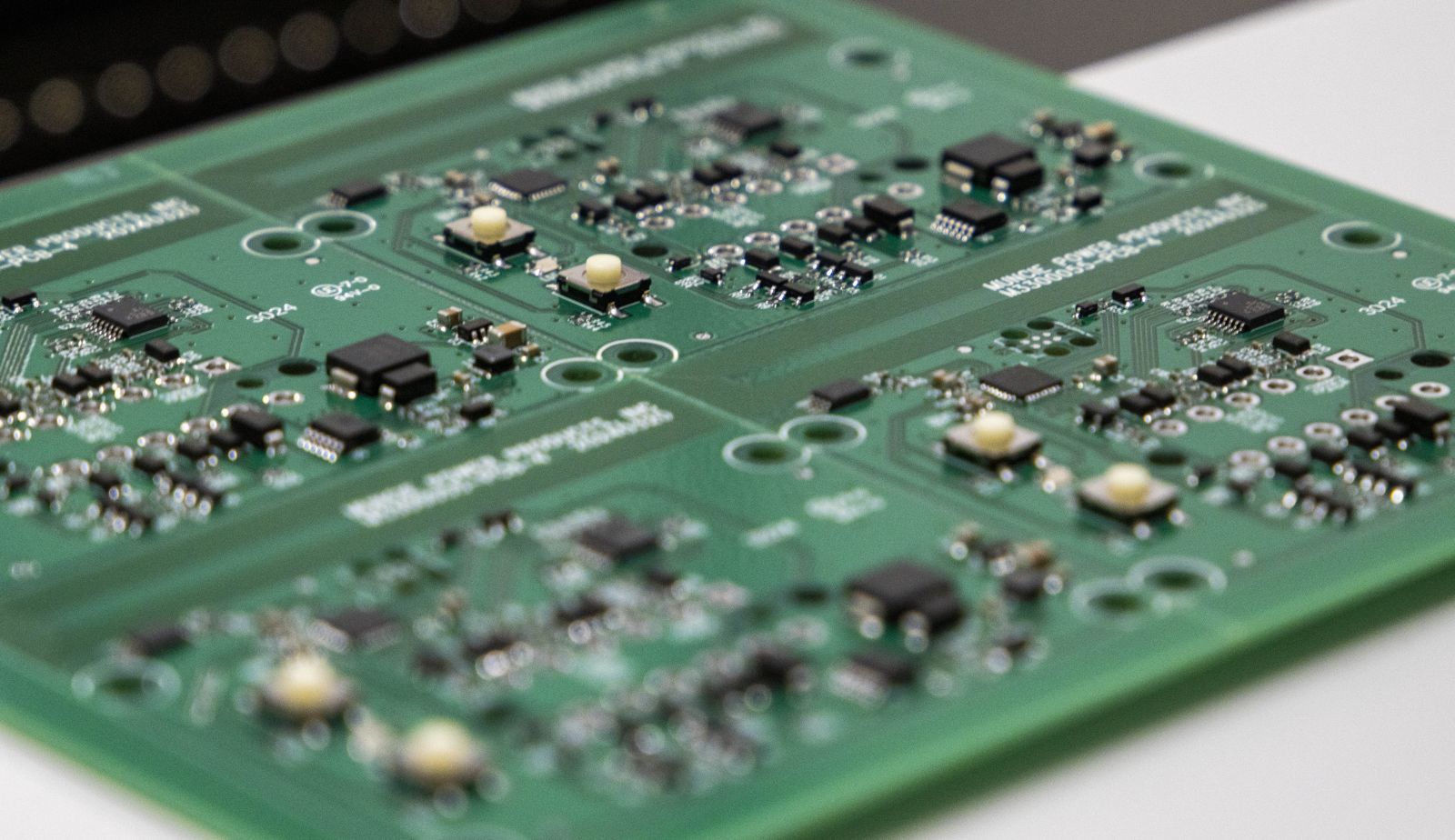
As truck chassis technology advances, so does the need for advanced electronic integration.
Muncie Power Products is working on innovative solutions tailored to customers' ever-evolving needs by establishing a state-of-the-art surface-mount technology (SMT) line, allowing us to transform raw electrical components into fully functional printed circuit board assemblies (PCBAs).
WHAT IS SURFACE-MOUNT TECHNOLOGY?
Surface-mount technology is the latest process for manufacturing PCBAs, which are used in nearly all electronic devices. Before surface mounting, circuit boards used through-hole technology (THT), which required components to be inserted through drilled holes in the circuit board using tails or leads. Alternately, SMT allows most raw components, such as resistors, capacitors, or integrated circuits, to be mounted directly to the surface of the board.
SMT provides several advantages over traditional THT. SMT requires fewer holes drilled in the board, and SMT components are often smaller than THT, which means more components can fit on a single board (i.e., higher circuit density). Additionally, SMT is often more cost-effective and faster compared to THT lines.
HOW IS A CIRCUIT BOARD MADE IN A SURFACE-MOUNT TECHNOLOGY LINE?
This new capability involves a highly automated production line. Starting with a raw printed circuit board (PCB), solder paste is applied, electrical components are placed, the assembly is inspected before being functionally tested, and then packaged into a finalized product.

Stencil printer
The stencil printer is responsible for transferring solder paste to a raw PCB. The “stencil” portion of this machine consists of a thin stainless layer that is laser cut specific to each circuit board.
As the stencil is placed upon the raw circuit board, a squeegee-like device applies solder paste through the openings of the stencil and onto the pads of the circuit board. This step is critical for bonding the electrical components to the board.
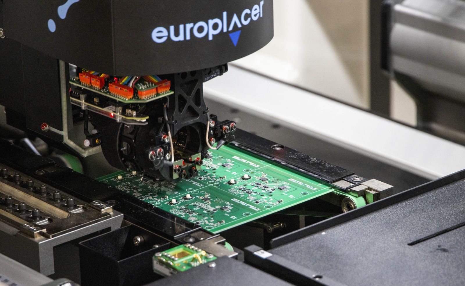
Pick and Place
Using high-resolution cameras aligning with fiducial, or alignment marks, on the board, the pick and place machine is responsible for precisely locating raw electrical components to the circuit board.
The dimensional data of each component is uniquely programmed within the machine. Once a design Gerber file is loaded and appropriately configured in the machine, components can be pulled from reals or trays to be positioned upon the board. To verify components are within specification, certain components can be electrically pre-tested by this machine before placement.
Our specific SMT machine advertises placement speeds of up to 15,000 components per hour.
Reflow Oven
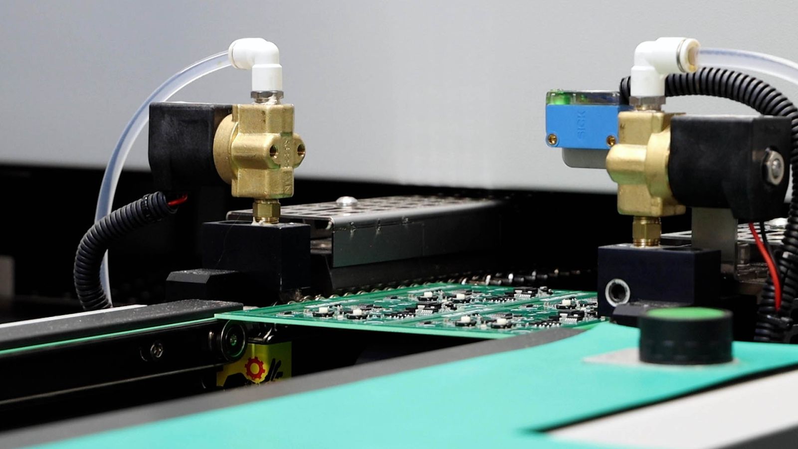
Once the components have been placed on the board, a conveyor will transfer the assembly through a reflow oven. This machine is equipped with several heating zones and requires a configured temperature profile per board design to ensure quality solder connections.
Automatic Optical Inspection Equipment
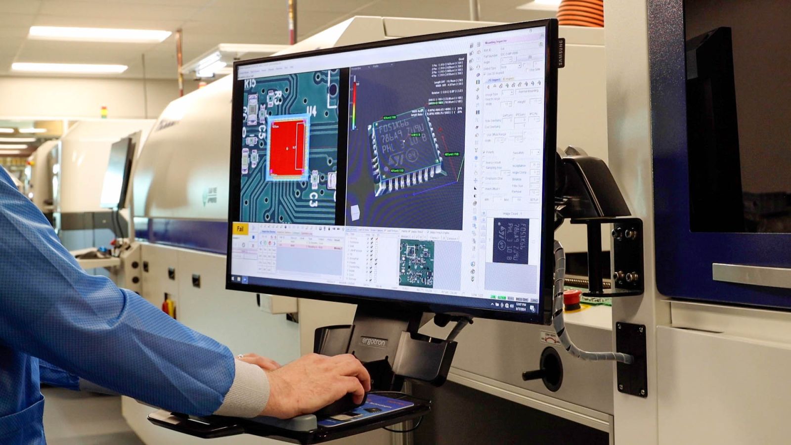
The automatic optical inspection (AOI) machine ensures accurate component placement. Again, using high-speed cameras, this machine efficiently captures numerous high-resolution images to create a detailed rendering of each PCBA.
By comparing against programmed design specifications, the machine can alert the operator to non-conforming placement. Furthermore, it can provide feedback on the quality of solder joints (i.e., it can spot if there are solder bridges between the legs of components).
Functional Testing and Assembly
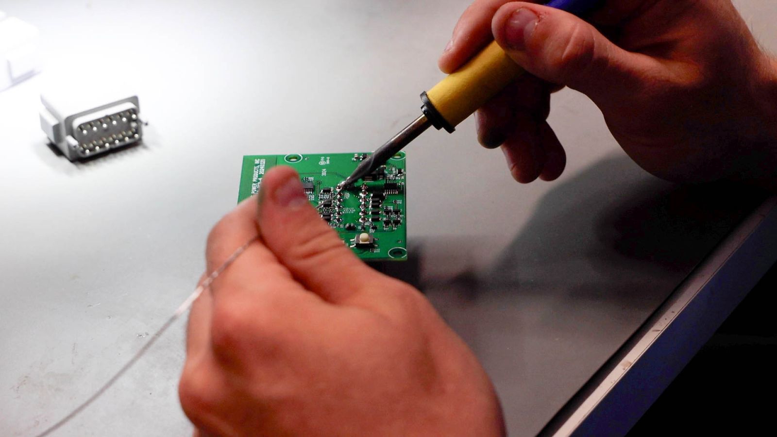
Following the AOI process, the PCBAs will route to other workstations. These stations may include board touch-ups, manually locating connectors, visual inspecting, and ultimately routing through a final functional test to verify all board I/O are functional and meeting product specifications.
Once tested, the product will be routed to the final assembly and packaging step.
HOW IS A SURFACE-MOUNT TECHNOLOGY LINE BENEFICIAL?
By instituting SMT, Muncie Power can better maintain tighter control over our supply chain, maintain better quality control over the product, reduce finished goods inventory, and enable us to better stock long lead-time semiconductors to better navigate industry disruptions.
This capability also allows us to rapidly develop prototypes, ensuring we stay ahead of the curve and support our customers more effectively with ever-changing demands.
WHAT PRODUCTS WILL BENEFIT FROM SURFACE-MOUNT TECHNOLOGY?
Electrical assemblies are integral to various products across Muncie Power, from modules paired with our power take-offs to sophisticated touchscreen controls in our electro-hydraulic control systems.
We will be running upwards of 12,000 boards annually for our current production needs.
Some of the products that will feature PCBAs include:
- SPD-2000 Modules
- ePTO Solution Modules
- RPM Control Modules on power take-offs for Ford
- Muncie Start® Modules
- Omni-System® Plus Controller
- Omni-System® Controller
- Omni-System® ESP Controller
- Omni-System® Primary and Secondary Modules
- Omni-System® Camera Modules
- Joystick Control Boards
With this new capability, Muncie Power is enhancing our offerings and shaping the future of mobile hydraulics and controls.


