

What to Know About Hydraulic Tanks
Hydraulic tanks are critical components in hydraulic systems across many industries, including refuse, vacuum, construction (such as dump trucks), and tow and recovery. These systems rely on hydraulics to perform work, and the tank plays a key supporting role.
Hydraulic tanks serve three main purposes:
- Store oil until the system requires it
- Help cool the oil
- Provide a place for contaminants to settle out of the oil
When selecting a hydraulic tank, key considerations include material, shape, volume, location, and construction.
MATERIAL
Oil tanks can be constructed from steel, stainless steel, aluminum, or polyethylene. Each material has benefits and drawbacks that should be evaluated when choosing a tank.
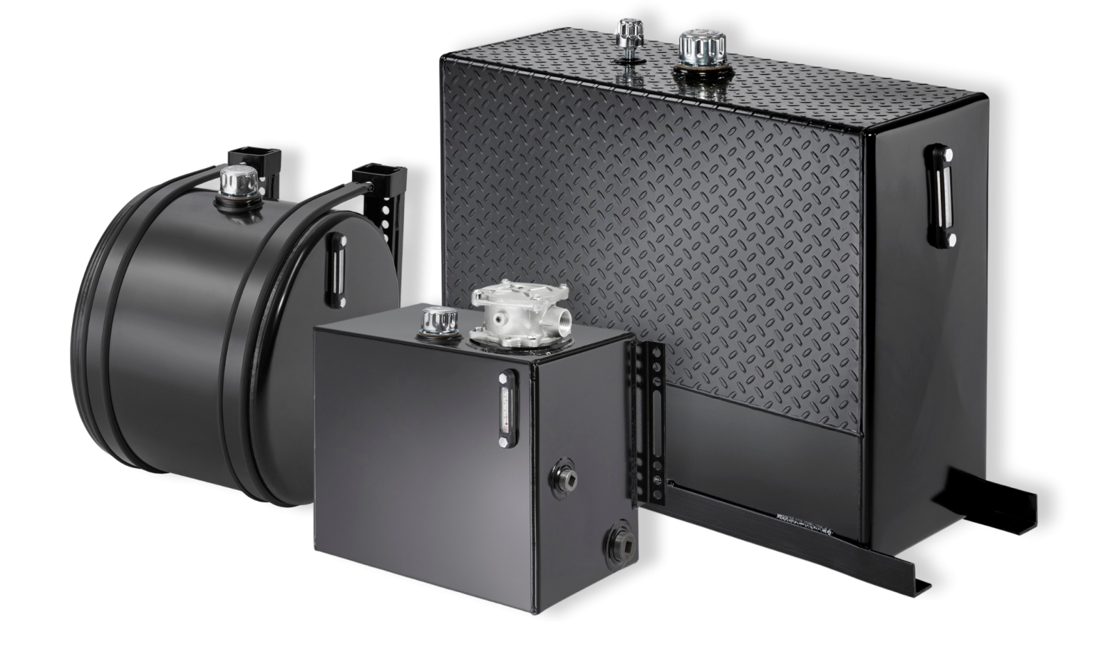
Steel & Stainless Steel
Steel dissipates moderate amounts of heat and is relatively easy and economical to fabricate, as steel plate is readily available and inexpensive. Steel is also heavy.
However, steel tanks are susceptible to moisture condensation and rust. This is because steel is primarily made of iron, which oxidizes when exposed to oxygen and moisture, commonly known as oxidation. Powder coating helps extend the life of steel tanks. To extend their service life, Muncie Power powder coats all steel tanks.
Stainless steel is another material option for hydraulic tanks and is commonly used for custom-made tanks. It is significantly more resistant to corrosion than mild steel and is also an effective dissipater of heat. Stainless steel is highly durable and offers strong resistance to abrasive materials.
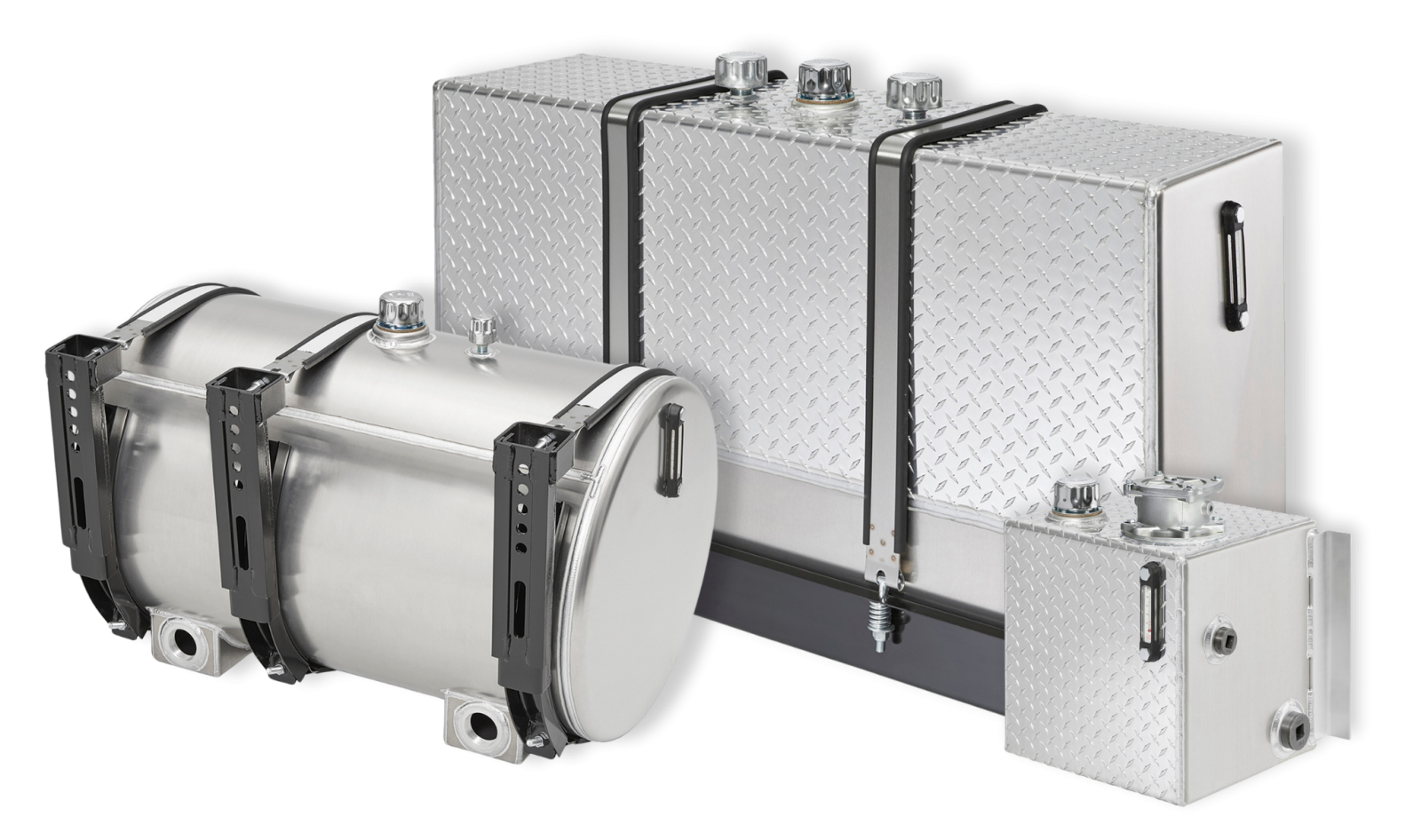
Aluminum
Aluminum is visually appealing and offers excellent heat dissipation—about three times the heat transfer rate of steel. It is often preferred by owner-operators who customize their trucks with premium options and custom paint jobs.
However, aluminum is expensive and requires a higher level of fabrication skill and routine maintenance.
Condensation can also cause aluminum to oxidize.
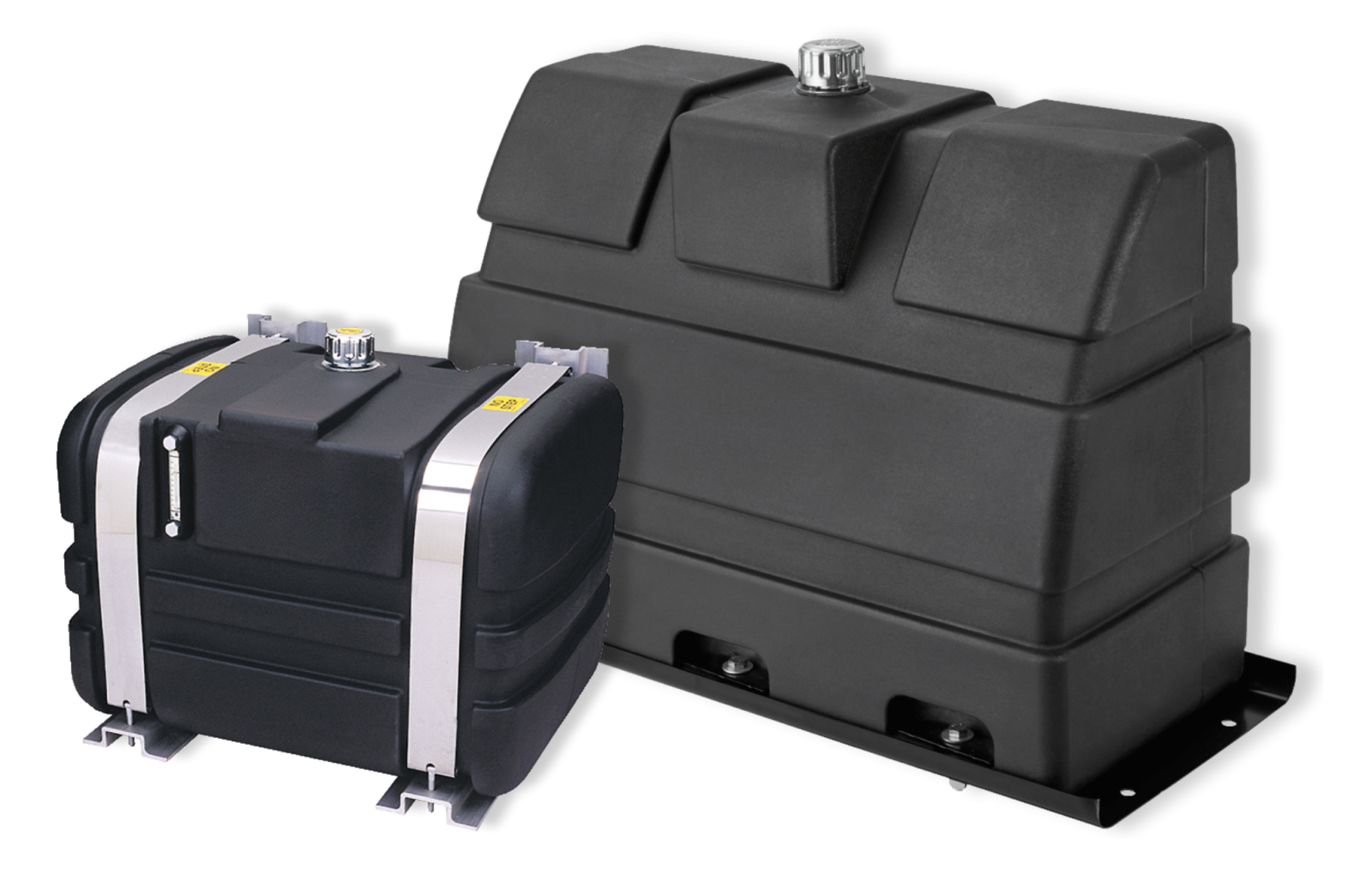
Polyethylene
Polyethylene, often called poly or plastic, is lightweight and can be molded into various shapes and colors.
The manufacturing process does not generate contamination particles, and poly is less susceptible to moisture condensation.
However, polyethylene does not dissipate heat well and is not suitable for long duty-cycle applications like hydraulic motor drives or live floors. It is better suited to dump, roll-off, or ejector applications with short duty cycles.
SHAPE
Standard tank configurations include rectangular (upright), box, and cylindrical designs. Steel and aluminum can be used for all three shapes, while polyethylene is generally limited to upright and box designs.
Often, the mounting location on the truck dictates the tank shape:
- Rectangular tanks (upright mounts) are typically installed behind the cab.
- Box-style tanks (side mounts) are mounted along the chassis side.
- Cylindrical tanks (saddle mounts) use saddles to attach to the chassis.
If standard tank shapes (or capacities) do not fit an application, custom tank options are available and are designed to fit.
RELATED: Custom Tanks: How it Works and Process
VOLUME
Tank size must ensure an adequate oil supply. As a starting point, consider these general guidelines:
- For systems using cylinders as actuators, tank capacity should equal the oil volume required to fully extend the cylinders, plus a 20% reserve (or 4–6 inches of extra oil level in the tank).
- For systems using hydraulic motors as actuators, tank capacity should be about twice the system’s operating flow rate.
These guidelines are influenced by ambient temperature, duty cycle, frequency of use, and other conditions. The primary goals are to maintain a sufficient oil supply and manage heat.
Calculating Tank Capacity
Calculating tank capacity is straightforward geometry.
For box or rectangular tanks, multiply length × height × width (in inches) to obtain the volume in cubic inches. Divide by 231 to convert to gallons.
For cylindrical tanks, use: πr² × length ÷ 231 = gallons
Keep in mind that this example does not account for tank wall thickness, which slightly reduces the actual capacity.
Other factors—such as the air gap, baffles or support structure, port size and location, and the minimum oil level above the port to prevent uncovering or a vortex effect—also reduce usable volume. As a result, the usable capacity of a tank is generally considered to be about 80% of its total calculated volume.
LOCATION
Tank placement is equally important. Because the tank’s main job is to feed oil to the pump, the ideal location is close to and directly above the pump inlet.
This is often feasible in industrial installations but difficult in truck-mounted systems. When the pump is mounted on the vehicle front or on top of the engine, the tank outlet is usually several feet away and below the pump inlet.
In these cases, the inlet hose should be oversized and routed as straight as possible to reduce the risk of pump cavitation. Sometimes a sealed, pressurized tank is required.
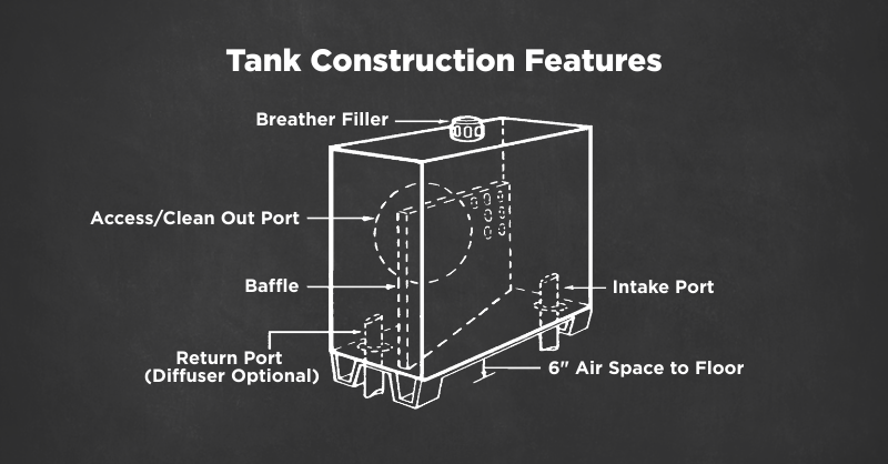
CONSTRUCTION CONSIDERATIONS
The tank must breathe—taking in and exhausting air as the fluid level changes—so it needs a vent or breather cap. An improperly vented tank can starve the pump, so the breather should be cleaned regularly.
Returning oil should always enter the tank below the oil level, either by placing the return port at the bottom or routing the flow through a standpipe to the bottom.
Oil entering above the fluid level can cause foam and air bubbles (aeration), which may be drawn into the system and cause sluggish or jerky operation. A diffuser will further dissipate oil flow below the fluid level and effectively manage high-volume return flows common in dump applications.
Porting
Port placement and size are also crucial. The pump inlet and return ports should be located at opposite ends of the tank so the returning oil can cool before being reintroduced into the system.
Baffles can be used to keep warmer return oil away from the pump inlet and to control sloshing. They should direct the return flow toward the tank walls, where heat can dissipate.
Ideally, the oil should follow the longest practical path to the outlet port. To keep settled contaminants from re-entering the system, the outlet port should be raised slightly above the tank bottom.
RELATED: Keep Your Oil Clean: Contamination and Its Many Forms
Other Considerations
Low-profile tanks may be attractive for ground clearance, but they can expose the pump inlet to the atmosphere when operating off-road or on an incline. In addition, an inlet line vacuum may create a vortex and draw air into the system.
Temperature and fluid level gauges, fill screens, clean-out ports, and magnetic drain plugs are all useful accessories for hydraulic oil tanks.
In piston pump systems, pressurized tanks are often used to improve inlet conditions; pressures of 3–4 PSI are typical.
A common practice, but not recommended, is to split a 100-gallon fuel tank into two compartments, using one for fuel and one for hydraulic oil. This practice presents several potential problems: the fluids must remain completely isolated, diesel fuel can be mistakenly added to the hydraulic oil, and there is often no design provision (such as a diffuser) to manage high-volume return flow, as in dump trailer applications.
When properly sized, positioned, and equipped with the right accessories, a hydraulic tank can significantly reduce heat, minimize contamination, and ensure reliable pump inlet conditions—ultimately improving the efficiency, durability, and safety of the entire hydraulic system.