


Directional Control Valves: A Guide to Selection and Specification
Directional control valves are the traffic directors of a mobile hydraulic system.
They route oil to the function an operator wants to move—such as a dump bed, snow plow, winch, auger, spinner, or utility bucket—and keep other functions still.
Once you understand a few core terms and the basic valve sections, specifying the right configuration becomes much more manageable.
What Does a Directional Control Valve Do?
A hydraulic pump creates flow, but the directional control valve determines where that flow goes and when. Without a valve, oil could reach multiple cylinders or motors at the same time. The valve gives the operator controlled movement by opening a path to the selected function while managing the return path for the oil.
On a tow truck, for example, the valve can direct flow to slide the bed, tilt it, or run the winch. The same principle applies across many vocational vehicles: the valve converts an operator command into a specific hydraulic movement.
Open Center vs. Closed Center
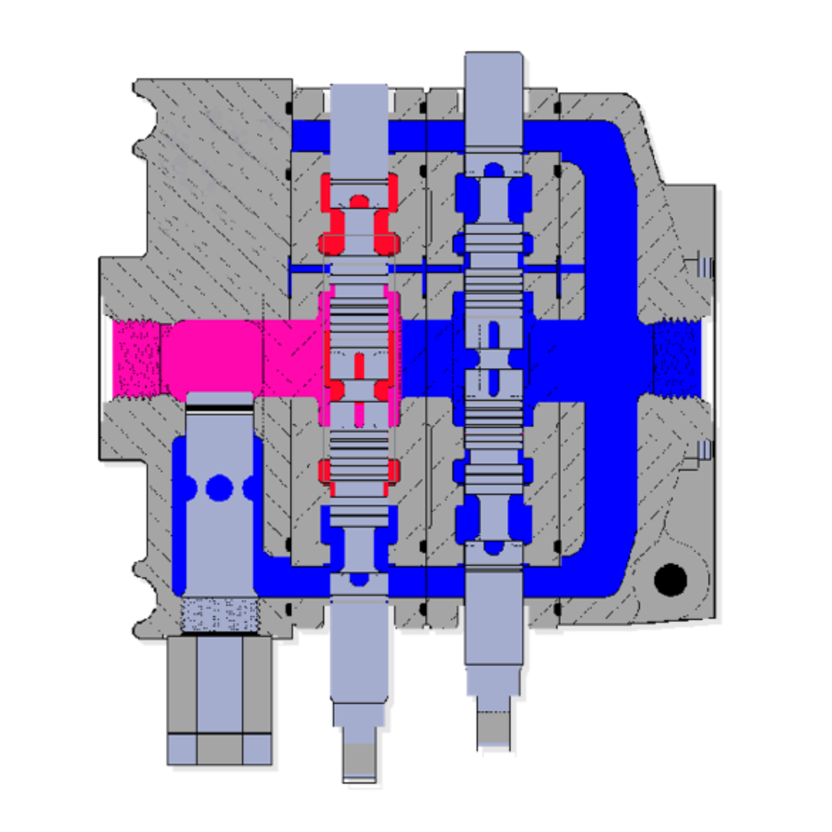
Open center valves
With every handle in neutral, an open-center valve provides a continuous path through the valve and back to the tank. Oil circulates from the tank to the pump, through the valve, and back to the tank when no work is being performed. This is the common arrangement for mobile equipment such as tow trucks, garbage trucks, and dump trucks, and it is typically paired with a conventional gear pump.
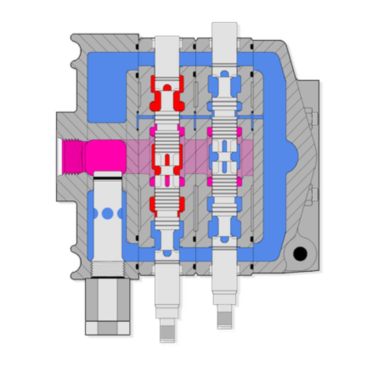
Closed center valves
In a closed center valve, the neutral position blocks the flow path. Because the oil cannot simply return to the tank, this design must be matched to a suitable pump (typically a pressure-compensated or load sensing piston pump). Pairing a closed center valve with a conventional fixed-displacement gear pump can deadhead the flow and should be avoided.
Choose the Spool for the Function
Each work section contains a spool whose internal lands and grooves route oil in a specific way. The spool must match the component it controls.
Single-acting cylinder spool
A single-acting cylinder uses hydraulic pressure to move in one direction and gravity or an external load to return. A dump body is a common example: the pump raises the body, while gravity lowers it and pushes oil back to the tank. Only one work port is normally connected to a hose.
Double-acting cylinder spool
A double-acting cylinder requires pressure in both directions. A snow plow angle cylinder, for example, must be powered to move left and powered again to move right. Both work ports are used so flow can be reversed between the two sides of the cylinder.
Motor spool
A motor spool supports a hydraulic motor that produces rotary motion. Typical applications include augers, spreader spinners, winches, and rotating bucket mechanisms. Because motor and cylinder spools route return flow differently, substituting one for another can cause poor or incorrect operation.
Know the Main Parts of a Stack Valve
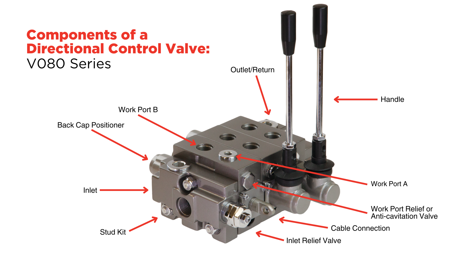
Many mobile directional control valves are built as modular stack valves. Individual components are placed together on tie rods, allowing the valve to be configured for a specific machine and modified later.
- Inlet: Receives pump flow and normally contains the system’s main relief valve.
- Work sections: One section is used for each hydraulic function. A valve assembly may contain a single work section or several.
- Work ports A and B: These connect the work section to a cylinder or motor. On the valves discussed in the training, port A is nearest the handle side and port B is farther away.
- Control side: The spool may be shifted manually, by cable, pneumatically, or electrically.
- Back cap positioner: Determines whether the spool springs back to neutral, stays in a detented position, or combines those behaviors.
- Outlet: Returns oil to the tank or carries pressure onward to another valve.
- Stud or tie rod kit: Holds the stack together; its length depends on the number of work sections.
Specify the Inlet and Relief Valve
The inlet is usually straightforward, but two decisions matter.
First, decide whether the inlet should include a relief valve. A relief-equipped inlet is the standard and generally recommended choice because it protects the system from excessive pressure.
Second, select a relief valve range that includes the desired preset pressure. The range code and preset value must be compatible; a preset outside the selected adjustment range is not a valid combination. Product literature may omit uncommon options; consult the manufacturer when the required range or setting is not shown.
Although an inlet may provide two connection locations for routing flexibility, only one inlet port is used; the unused port is plugged.
Select the Work-Section Controls
After choosing the spool, determine how the operator will shift it. Common options include a lever cap arrangement for a manual handle, a spool eye for direct cable connection, pneumatic actuation, and 12 V electrical actuation. A lever cap option can also provide a useful manual backup when the primary control is air or electric.
For manual or cable operation, the positioner defines how the control behaves.
A spring return positioner brings the handle back to neutral when released.
A detent positioner holds the selected position after the operator lets go.
Combination positioners can provide detent in one direction and spring return in the other.
The correct choice depends on the machine function and the operator’s expected sequence. Some work sections also accept port relief or anti-cavitation options. These are application-specific and require a clear understanding of the load, pressure setting, and circuit behavior.
When Do You Need Power Beyond?
Power beyond, also called high pressure carryover (HPCO), is needed when pump flow must pass from one valve assembly to a second valve downstream. When the first valve is in neutral, its outlet must carry pressurized flow to the next valve rather than sending all flow directly to the tank.
If every machine function is contained in one valve stack, power beyond is usually unnecessary. If the hydraulic system has two separate valve assemblies in series, the upstream valve normally requires a power beyond sleeve. The dedicated tank port still provides a low-pressure return path, while the power beyond port feeds the next valve.
This feature is often field convertible: a sleeve can be added when another valve is installed later, or removed and the port plugged when it is no longer required.
Valve Specification Checklist
Before using a valve builder or assembling part numbers, answer these questions:
- Is the hydraulic system open center or closed center?
- What type of pump does it use?
- How many separate functions require work sections?
- For each function, is the actuator a single-acting cylinder, double-acting cylinder, or hydraulic motor?
- How will each section be controlled: handle, cable, air, or electric?
- Should each control spring back to neutral, remain detented, or use a combination?
- What relief valve range and preset pressure does the application require?
- Is a second valve located downstream, making power beyond necessary?
- What tie rod kit length matches the final number of work sections?
When inspecting an existing valve, a work section with one connected port and one plugged port usually indicates a single-acting circuit. Two connected ports could indicate either a double-acting cylinder or a hydraulic motor. Confirm what the section operates before selecting a replacement.
Ordering and Assembly
A modular valve assembly may not have one model number that represents the complete build. Instead, the inlet, each work section, outlet, tie rod kit, and optional handles can each have separate part numbers. Confirm whether the supplier should assemble the valve before shipment; otherwise, the components may arrive individually packaged.
An order number or identification label can be valuable when servicing an existing valve. Even when the full component list is not printed on the valve, the manufacturer may be able to use that number to retrieve the original configuration.
The Bottom Line
Directional control valves are easier to specify when you handle each decision in sequence.
Start with the hydraulic system type, match every spool to its actuator, choose the control and positioner behavior, determine whether power beyond is required, and size the tie rod kit for the final stack.
That foundation makes online valve building tools more useful and helps ensure the finished valve performs exactly as the machine requires.


