

How Does a Hydraulic Gear Pump Work?
To begin to understand how a gear pump works, let’s first define what a gear pump is.
Here is one simple definition: It is a device that takes the mechanical energy of the prime mover (usually a power take-off) and converts it to fluid energy in the form of oil flow.
A gear pump cannot act on its own; it must be driven by something. On a mobile work truck, the main prime mover is usually a power take-off. A couple of other prime movers could be a belt, normally running off the engine, or a driveshaft, often attached to the crankshaft of the truck.
An important fact about gear pumps is also brought up in the definition of a gear pump:
Gear pumps produce flow. That is their only job.
A large misconception is that gear pumps also produce pressure. The reason why is that it takes both flow and pressure to accomplish hydraulic work.
Flow equates to how fast the work gets done, and pressure equates to the force to be able to do the work.
But a gear pump does not produce pressure; it only produces flow.
Where does the pressure in the hydraulic system come from?
It comes from resistance to the flow of oil. The more resistance, the higher the pressure.
So, if the gear pump does not produce pressure, what does it do with it?
It tolerates it.
INSIDE THE GEAR PUMP
Now, back to the question: How does a hydraulic gear pump work?
We are going to focus on the workings of a gear pump.
GEARS
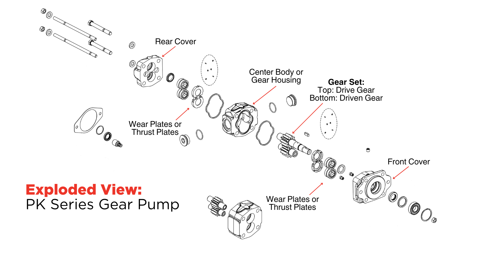
In a gear pump, there are two gears: one is called the drive gear, the other is called the driven gear.
The driven gear has a shaft sticking out of the pump that would be attached directly to the power take-off, or a pulley attached to a belt, or a yoke attached to a driveshaft driven by the crankshaft of the truck. The driven gear spins as moved upon by the prime mover, and this in turn spins the driven gear.
PORTS
A gear pump also has ports on the external body of the gear pump. These ports would have hose and fittings attached to them.
A lot of gear pumps today will often have two ports on the rear of the gear pump and two ports on the side of the gear pump.
The user would only use two of these ports, either the rear or the side, or one of each.
This is usually decided upon by the best routing of the hose based on clearance.
HOSE AND FITTINGS
The supply hose, more commonly referred to as the inlet, feeds the gear pump hydraulic oil from the tank. The outlet hose then supplies that hydraulic oil from the gear pump to the hydraulic system to perform the work.
At this point, it would be good to know how a gear pump produces its flow.
The gears spin as a direct result of input from the prime mover. A thing to note here is that the gear pump just produces flow because of its gears turning. The gear pump is not designed to suck or draw the oil from the tank; its internal design is for oil to be gravity-fed to the gear pump.
So, in a good hydraulic system design, the tank will be above the gear pump, as close to the gear pump as feasible, and the hose leading to the gear pump as large as possible. When a gear pump is not fed enough oil and tries to create a vacuum to suck oil, a condition known as cavitation can happen, which will quickly damage a gear pump.
RELATED: Hydraulic Pump Cavitation: What is it and How Can You Prevent it?
HYDRAULIC OIL
How does the oil go through the gears?
If you refer to the diagram video above, you will notice that the two gears spin in opposite directions. In the gear pump picture video above, the inlet, or the hose that is attached to the tank that is feeding the gear pump, would be the port on the left. This is common as it is the larger of the two ports.
When the hydraulic oil encounters the gear teeth, it is trapped between the pockets and the gear pump housing and carried around the outside of the gear until it reaches the port on the opposite side of the gear pump. This port would be the discharge, or pressure, port, more commonly called the outlet.
As the teeth mesh again, the trapped oil is forced out of the gear pump through the outlet port. Because of the gear pump’s continuous rotation, the gear pump is able to deliver a steady, metered flow of hydraulic oil as it moves the hydraulic oil through its core. The outlet port is what feeds the hydraulic system. This could be connected to a directional control valve, or directly to a cylinder, or a motor, that will turn the fluid power back into mechanical energy to accomplish the task.
A gear pump, at its core, is an amazingly simple device. There are a few moving parts, and they are very serviceable, as shown below.
Due to the tight tolerances of the gears spinning within the gear pump, two things should be noted.
No matter how tight the tolerances are, no gear pump is 100% efficient. A slight bit of oil will slip past the gear teeth. On average, a brand-new gear pump is about 90% efficient. Any inefficiency will show up in the system in the form of heat.
A second thing to note is that wear and tear over time will cause the gear pump to become less efficient. Eventually, a worn gear pump would have to be rebuilt or replaced. If a system were showing excessive heat or not working as it once did, both could be signs that it is time to replace the gear pump.
But you should get many years of usefulness from a pump if the following factors are observed:
- making sure the gear pump always has adequate amounts of oil being gravity-fed to it,
- not allowing the hydraulic oil to get above 140º F (60º C), as this can damage the seals within the gear pump, and
- operating the gear pump within its parameters.
PARAMETERS OF GEAR PUMPS
Let us discuss the parameters of the gear pumps.
Gear pumps have limits when it comes to speed and pressure tolerances.
All gear pumps have a minimum speed and a maximum speed.
The minimum speed does not mean the gear pump will not work below that speed, but it would be much less efficient below that stated speed.
The maximum speed of a gear pump would be the evaluated speed at which a gear pump is still operational. Operating consistently at that maximum speed, or pushing it above that speed, is where the gear pump would likely fail. Operating your gear pump within the tested parameters is essential for the longevity and usefulness of the gear pump.
Gear pumps also have a stated maximum pounds per square inch (PSI) tolerance.
This is the pressure that the gear pump was designed to withstand before becoming damaged.
When a gear pump sees more pressure than it was designed to withstand, the gears can be pushed into the side of the housing walls, and/or the gear pump shaft can break.
There is a correlation between the size of the gear pump and its maximum speed and maximum pressure tolerance. Typically, the larger the gear pump, the lower its maximum speed and the less pressure it can tolerate. Most gear pumps commonly have a pressure rating of 3,000 PSI or less.
RELATED: Types of Hydraulic Pumps
A gear pump only has one job: to produce flow through the hydraulic system.
When acted upon by a prime mover and when operated within the evaluated parameters, a gear pump will move oil throughout the hydraulic system, allowing you to accomplish the tasks at hand.