

How to Identify a Power Take-off and Shaft Extension for Allison 10-Bolt Transmissions
This article is focused on spec'ing out an A20 Series PTO and EX Drive shaft extension for Allison 3000 and 4000 RDS Series transmissions.
1. Identify the transmission
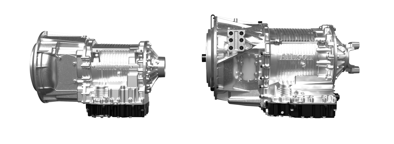
Muncie Power's shaft extensions fit with Allison 3000 and 4000 RDS Series transmissions. There are options for standard transmissions as well as ones with a retarder, a cooler, or both. If the transmission model number is unknown:
- Locate the transmission data plate on the transmission body. While it will not have the model number listed, it will have a serial number.
6510 = 3000 Series
6610 = 4000 Series
Keep in mind that designations like this are generally accepted; however, not all transmission models follow this kind of structure such as remanufactured transmissions. If you are unsure of the type of transmission, refer to the chassis manufacturer or an authorized Allison dealer.
2. Choose which side of the transmission the PTO will be mounted on
Factors that affect which side of the transmission to use include:
- Size of the hydraulic pump being used
- Interferences on the back end of the transmission (retarder, cooler)
- Transmission opening(s) available
- Available space surrounding the PTO opening
It is important to note that if working on a top opening on a 4000 RDS Series transmission that space is very limited and not all power take-off (PTO) and shaft extension combinations will work. Refer to the correct Quick Reference (QR) Catalog page for available combinations for this opening. See below for proper QR pages.
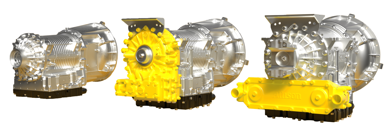
3. Identify any possible interferences such as a retarder and/or an external cooler
Next, identify if the transmission in question has an integral cooler, retarder, or both. Visual inspection on the rear of the transmission will confirm if these are present. If unsure, the serial number will also give more details on transmission features. Refer to an authorized Allison dealer to assist further with those details.
This step is crucial in the process as these additions to the transmission impact the shaft extension part number that matches the application. Having a cooler and/or retarder requires a longer shaft extension, as well as a different assembly arrangement on the PTO. Failure to identify will result in fitment issues at installation.
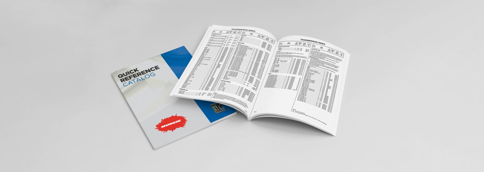
4. Use the Quick Reference Catalog
At this point in the process, the QR page will finish the process of ensuring that the correct part number is identified. For the Allison 3000 RDS Series, refer to ALLI-05 in the QR. For the Allison 4000 RDS Series, refer to ALLI-06 in the QR. Both ALLI-05 and ALLI-06 have additional pages marked with “X” at the end (i.e., ALLI-05X and ALLI-06X). These pages have the corresponding shaft extensions.
The tables on these QR pages are to be used exactly as intended. Do not deviate from the model number constructions listed based on the transmission. Deviation from this table will result in incorrect part numbers and issues with installation. The QR page will list the correct assembly arrangement based on which side of the transmission the PTO is going to be mounted.
5. Select which shaft type will be used on the pump output
As it is required to identify any PTO, ensuring the correct shaft output type is necessary for the correct shaft extension. The output shaft type is built into the shaft extension model number.
The missing part of the model number at this step is the output shaft type:
XSMC-A30XX-X3**XX
Identify the output shaft type needed and fill in the blank. This will complete the shaft extension model number.
| EX Shaft Output Shaft Code Designation | Description |
|---|---|
| B | SAE B 7/8" 13T Spline |
| C | SAE C 1.25” 14T Spline |
| I | DIN 5462 |
| P | SAE BB 1" 15T Spline |
| EX Drive Mounting Flange | Description |
|---|---|
| B | SAE B 2/4 Bolt |
| C | SAE C 2/4 Bolt |
| I | DIN 5462 |
Pay close attention to the footnotes for shaft extensions. The footnotes include important information that can affect installation.
6. Build the part number
Like the shaft extension, the QR page will complete the PTO part number as well. The QR page will also identify any PTOs where a shaft extension is not available due to clearance. Select the type of PTO needed, identify the speed of the PTO, and then refer to the table for the remaining model construction.
Example:
A20-A1007-HX3CBPW
The last four digits of the model number in the example above should not change. The output shaft and flange combination on the PTO model number corresponds to how the shaft extension mounts to the PTO. The special feature code at the end of the model number must be “W” giving the PTO a wet spline option to ensure that the shaft extension is mounted correctly. All of Muncie Power’s shaft extensions have a wet spline design to enhance spline durability resulting in longer life for both the PTO and shaft extension.
Key Takeaways
- The QR page will be the primary resource for identifying the correct shaft extension.
- Deviating from the recommended model number constructions on the QR pages will result in fitment issues at installation.
- Ensure that the output shaft and output flange correspond with each other. Failure to do so will result in pump installation issues.
- Utilize the online PTO builder for additional assistance.