

How to Install and Program the PTO RPM Module on Ford Trucks
Muncie Power Products launched the F22 Series power take-off (PTO) for the model year 2024 Ford F-650 and F-750 diesel trucks. In the past, PTOs for Ford would include a wiring harness that contained a relay, diodes, resistors, and a potentiometer. When opening up an F22 Series activation kit, you will not find any of those items, though—you will find the new PTO RPM Module.
The PTO RPM Module was designed to greatly simplify the often cumbersome job of wiring and then adjusting engine speed settings during a PTO installation on Ford trucks. The module connects to the Ford SEIC connector under the hood, the rocker switch (either the included Muncie Power switch or a Ford factory PTO switch), the PTO solenoid, and the pressure switch. All connections are streamlined into a plug & play setup. Once everything is plugged in, the module can be programmed.
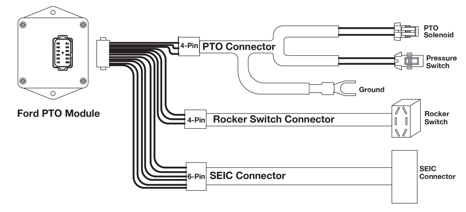
Figure 1. The Muncie Power PTO RPM Module harness diagram.
As always, before starting the installation of the wiring harness, be sure to disconnect the truck battery.
It is recommended that the PTO be installed on the transmission prior to starting the installation of the module. The module can sense an open circuit on the PTO solenoid, so the solenoid must be connected for the module to be programmed.
Next, we’ll go over how to install the PTO RPM Module. Then we’ll go over how to program the PTO RPM Module for either stationary or dual mode.
STEP 1
HARNESS SECTIONS
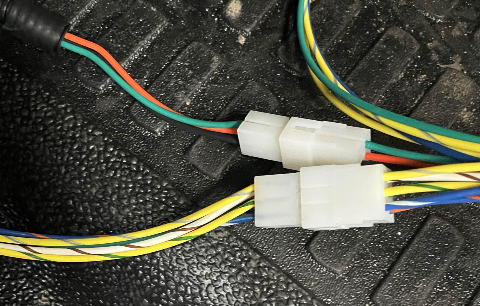
Figure 2. The 4-pin (top) and 6-pin (bottom) connectors.
Each individual section of the harness connects to the module side of the harness via 4-pin (PTO and rocker switch sections) or 6-pin (SEIC section) connectors.
The harness is constructed this way to allow for the harness to be easily routed through the firewall pass through.
The section for the rocker switch (4-pin) can be left on the module section, as both of those items will be installed inside the cab.
STEP 2
Ford Stationary Elevated Idle Control (SEIC) Connection
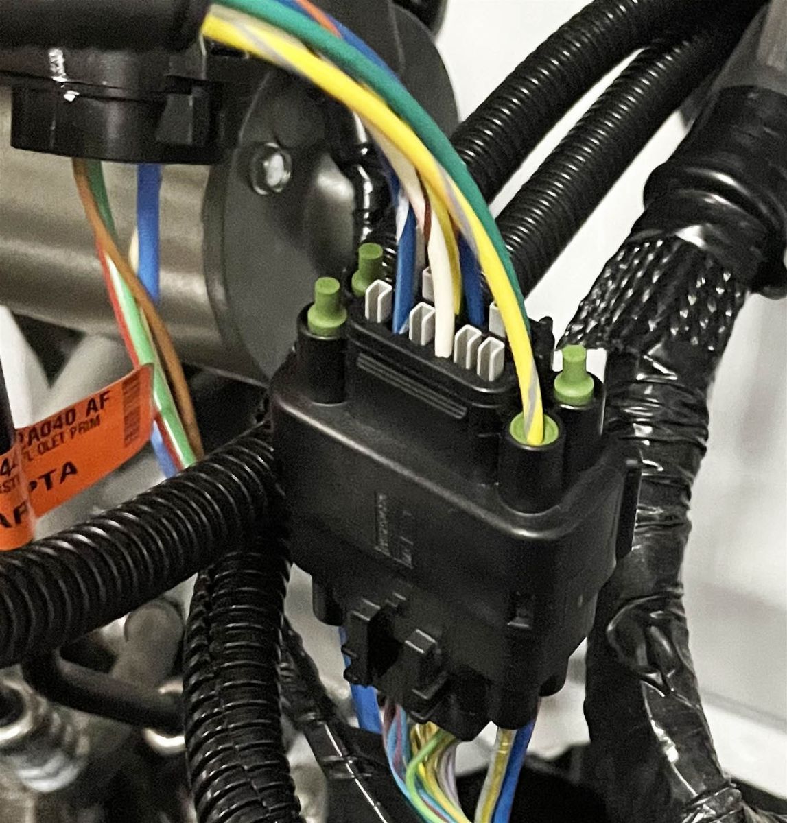
Figure 3. The Ford SEIC connector with Muncie Power harness installed.
The Ford SEIC connector can be found under the hood on the driver’s side, close to the firewall. This connector has 16 pins and will come from the factory with a matching connector installed, with blunt-cut wires included for aftermarket PTO installations.
The Ford-provided connector with blunt cut wires can be removed and discarded, as the PTO RPM Module harness comes with a matching connector already installed on the harness.
STEP 3
PTO Pressure Switch and Solenoid Valve Connections
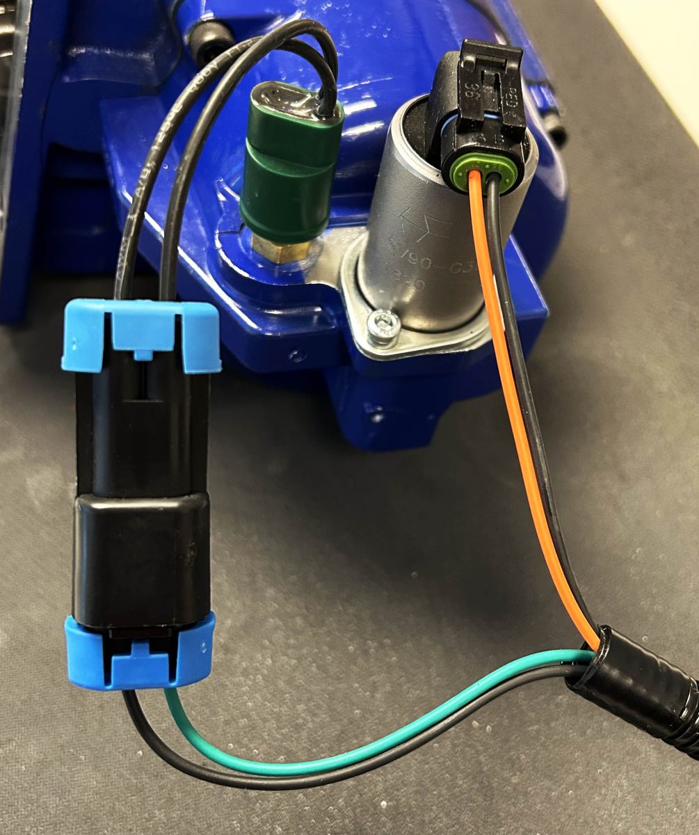
Figure 4. The pressure switch (left) and PTO solenoid valve (right) connections.
The PTO portion of the harness has two connectors for the PTO solenoid valve and pressure switch, respectively.
The connector with an orange wire and black wire goes to the solenoid valve, and the connector with a green wire and black wire goes to the pressure switch.
There is a fork terminal on the opposite end of the harness that connects to the ground. The best practice is to always connect directly to the ground terminal on the truck battery.
STEP 4
FIREWALL PASS-THROUGH
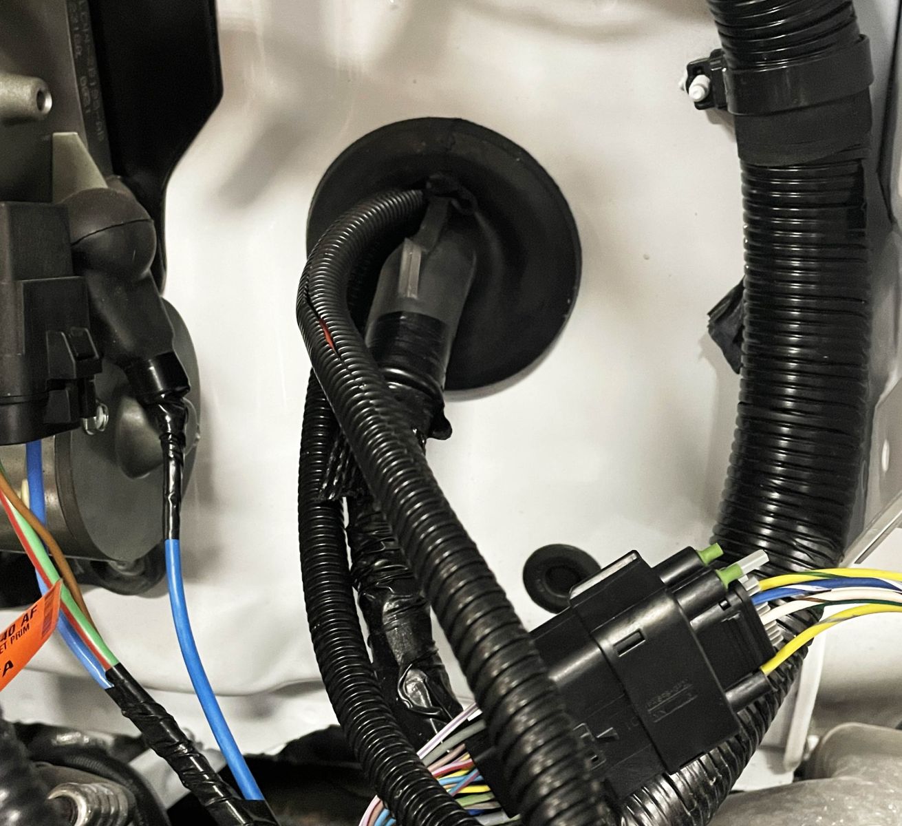
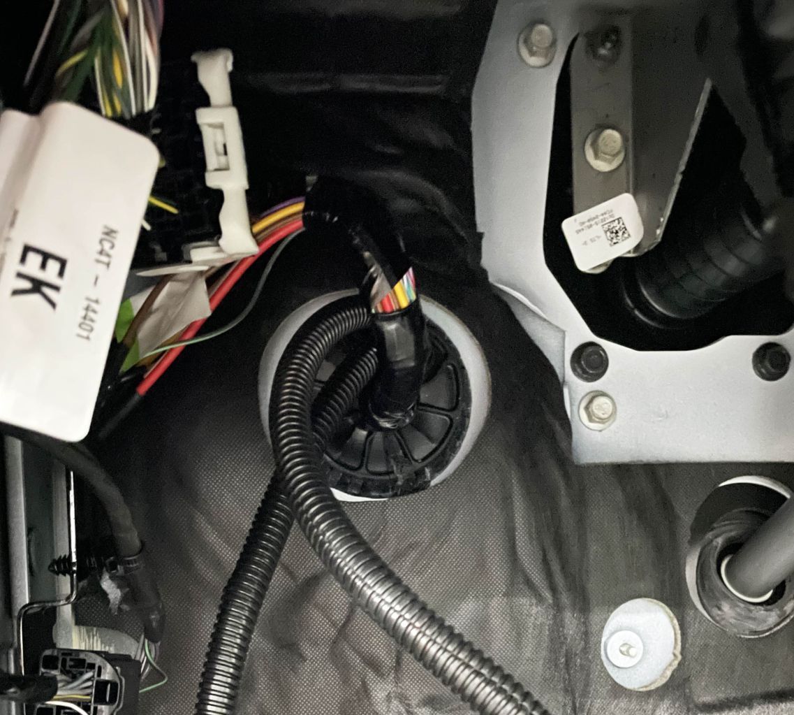
Figure 5. The firewall pass-through is shown from the engine side (left) and inside the cab (right).
After both the SEIC and PTO connections have been made, feed the ends with 4-pin and 6-pin connectors through the nearby pass-through for the in-cab connections.
For instances where the pass-through is not able to be used and a new hole needs to be added to the firewall, the harness includes grommets preinstalled on the loom. Most applications should be able to use the pass-through.
STEP 5
In-Cab Connections
For stationary mode
The module and rocker switch connections are both made inside the cab. Programming of the module requires access to the buttons on the back and must be done prior to mounting the module. The rocker switch can be mounted after the wiring connections can be made.
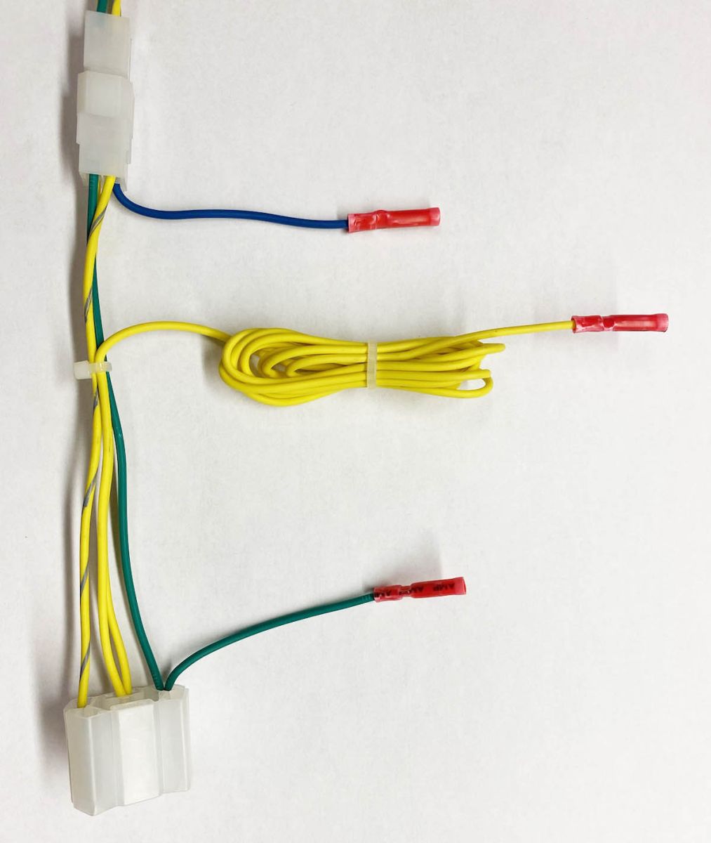
Figure 6. A single-mode switch harness.
There are two potential options for the rocker switch, depending on the shift type ordered on the PTO.
Single mode applications feature a 2-position rocker switch (ON/OFF), with the indicator light built into the switch itself. This switch comes from Muncie Power wired for a stationary application. A factory switch from Ford can also be used for single-mode applications. To use the Ford switch, connect the 12 V feed from the switch to the 56" blunt-cut yellow wire coming from the back of the rocker switch socket. A blunt-cut green wire is also included on the back of the switch socket for the installation of a stand-alone indicator light.
To convert the harness for a dual-mode application, cut the yellow wire going to pin #2 of the 4-pin connector and connect it to the blue wire that goes to pin #1 on the 4-pin connector.
For Mobile Mode
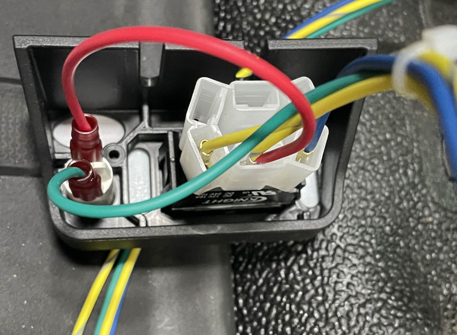
Figure 7. The back of the rocker switch connections for dual mode applications.
Dual mode applications feature a 3-position rocker switch (mobile ON, OFF, and stationary ON). The indicator light is separate from the switch. There is a red wire coming from the switch socket with a spade terminal that connects to one side of the indicator light. The other side of the indicator light will connect to the green wire with a spade terminal coming from the 4-pin connector. NOTE: The Ford factory switch cannot be used for a dual-mode application.
STEP 6
module connection
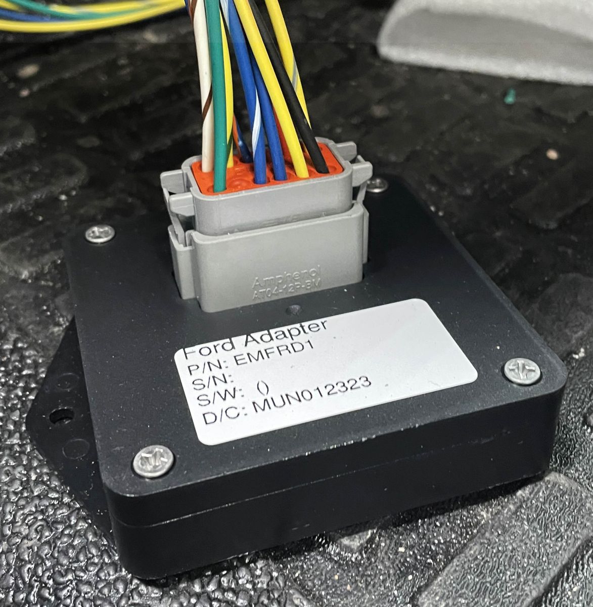
Figure 8. The PTO RPM Module with harness installed.
The final connection to be made is the module itself. Once again, programming of the module must be done before mounting the module under or in the dash. The truck battery can now be reconnected.
STEP 7
Module Programming
For stationary mode programming
- Start truck and turn PTO switch to ON or STATIONARY. The PTO indicator light should come on to indicate that PTO has been engaged. The truck must be in park with parking brake set.
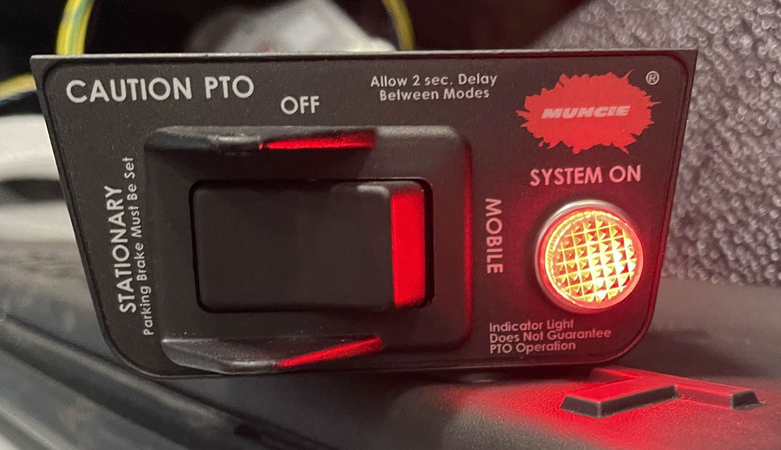
Figure 9. Switch on STATIONARY with the indicator light on.
- On diesel applications, the engine should ramp up to approximately 1,200 RPMs.
- Confirm that the LED on the back of the module is constantly on. This indicates that the module is sending 12 V to the PTO solenoid.
- Hold both + and – buttons on the module for 10 seconds. The LED on the module should blink for three (3) seconds to indicate that the module is in programming mode.
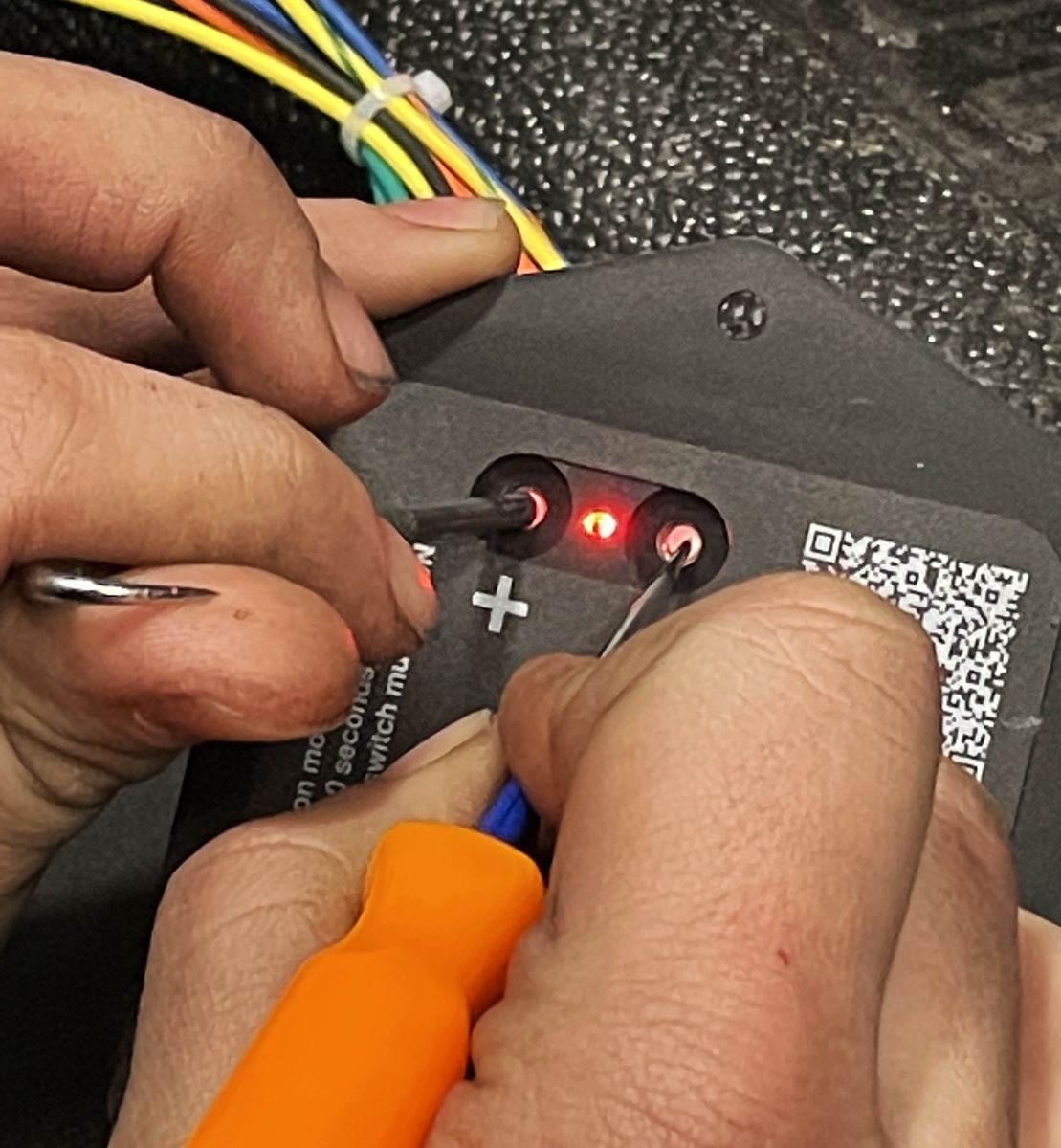
Figure 10. Hold both buttons for 10 seconds to enter programming mode.
- Adjust engine RPMs using + and – buttons. Each push will adjust the engine’s RPMs by approximately 50 RPMs on diesel trucks. The LED will flash indicating each RPM adjustment.
RELATED: [WATCH] Programming the PTO RPM Module
- Once the desired RPM setting is reached, hold both buttons for 10 seconds to exit programming mode.
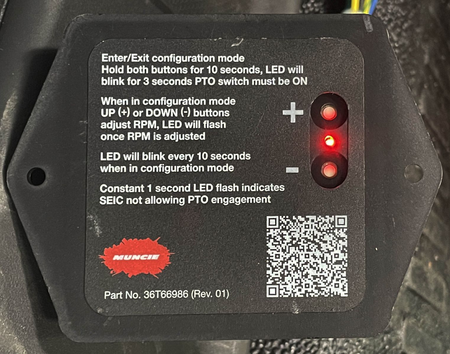
Figure 11. Back of the PTO RPM Module with LED on.
For mobile mode programming
- First, the truck transmission must be in park and the parking brake set to program the module.
- In mobile mode, the engine’s RPMs are controlled by the truck throttle pedal, and not by the module or SEIC circuit.
- There is a truck engine speed limiter feature which is adjustable via the module. The default setting of the module for mobile mode engine speed limit is 3000 RPMs, which is the engine’s redline.
- To adjust the engine speed limit, start the truck and turn the PTO switch to ON or MOBILE. The PTO indicator light should come on to indicate that PTO has been engaged.
- Hold both buttons on the module for 10 seconds. The LED on the module should blink for three (3) seconds to indicate that the module is in programming mode.
- The engine speed limit can now be lowered. Pushing the – button will lower the engine speed limit by 50 RPMs per push. For example, if the target engine speed limit is 2000 RPMs, the button would need to be pressed 20 times.
- The speed limit can be confirmed by using throttle pedal to raise the engine’s RPMs. The engine may overshoot the set point by 100–200 RPMs, depending on driving conditions.
- Once the desired RPM limit setting is reached, hold both buttons for 10 seconds to exit programming mode.
The programming of the module is now complete! The module can now be mounted in the desired location in the cab.
TROUBLESHOOTING DIAGNOSTIC CODES
If the PTO RPM Module does not engage the PTO, check for LED fault codes on the back of the module.
- Constant blinking, every 1/3 of a second, indicates a short circuit is present in the harness or the PTO solenoid circuit is open. Check that the 4-pin and 6-pin harness connections are correct and that the PTO solenoid is connected. (See Step 1 and Step 3.)
- Constant blinking, every second, indicates the SEIC is not allowing the PTO to engage. This likely means that the SEIC PTO enablement parameters (i.e., being in park, parking brake on, etc.) are not being met.
Learn more about enablement parameters for Ford trucks by clicking here. - If the light does not come on at all, the module is likely not getting power. Check for voltage at the rocker switch, then at the module.
- If the source of the problem cannot be identified, contact Muncie Power customer service.
Keep a copy of this article nearby by downloading and/or printing out a PDF version by clicking here.