

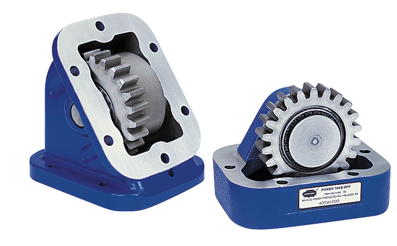
PTO Gear Adapters
Gear adapters mount between the vehicle transmission and power take-off, and can serve several purposes. Most commonly, adapters are used to change the direction of rotation of the PTO output shaft. They can also be used to space the PTO out and away from the transmission case. On some imported or non-SAE standard transmissions they allow for the mounting of standard 6-bolt power take-offs. Gear Adapters are available to fit most popular transmissions.
- Various body configurations: Can relocate the PTO output shaft to improve clearance for a driveshaft or direct-coupled pump
- Changes PTO shaft rotation: Matches PTO rotation to that of the driven equipment
- Standard and non-standard bolt patterns: Matches SAE standard PTOs to non-standard transmissions
-
Change Direction of Rotation of PTO Output Shaft and MoreWhitney VanKlaveren – Marketing Communications Coordinator
| Model No. | Figure | Gear Data | Dimensions | ||||
| Appl. | Teeth | A | B | C | D | ||
| 40TU6800 | Image | U68 | 22 | 2.917 (74.1) | 1.651 (41.9) | 1.084 (27.5) | 3.099 (78.7) |
| 40TU5700 | Image | U57 | 19 | 2.917 (74.1) | 1.651 (41.9) | 1.017 (25.8) | 3.166 (80.4) |
| 40TM6500 | Image | M65 | 24 | 2.917 (74.1) | 1.651 (41.9) | 1.065 (27.1) | 3.118 (79.2) |
| 40TA541 | Image | U68 | 20 | -- | 3.315 (84.2) | 1.085 (27.6) | 1.105 (28.1) |
| 40TF8500 | Image | F85 | 39 | 3.383 (85.9) | 0.617 (15.7) | 1.102 (28.0) | 5.046 (128.2) |
| Model No. | Figure | Loca. | Appl. | Teeth | B | C | D | E |
| 40TA0810 | Image | -- | U68 | 20 | 2.825 (71.8) | .642 (16.3) | 1.148 (29.2) | 1.750 (44.5) |
| 40TA0435 | Image | X | N81 | 22 | 2.307 (58.6) | .682 (17.3) | 1.108 (28.1) | 10° |
| Y | U68 | 20 | ||||||
| 4-TG7368-1 | Image | X | G73 | 22 | 2.307 (58.6) | .682 (17.3) | 1.122 (28.5) | 10° |
| Y | U68 | 20 | ||||||
| 40TG7368-2 | Image | X | U68 | 20 | 2.307 (58.6) | .682 (17.3) | 1.122 (28.5) | 10° |
| Y | G73 | 22 | ||||||
| 40TI8410-2 | Image | Y | I84 | 28 | 2.307 (58.6) | .653 (16.6) | 1.136 (28.9) | 10° |
| 40TM6568-1 | Image | X | M65 | 22 | 2.307 (58.6) | .682 (17.3) | 1.180 (30.0) | 10° |
| Y | U68 | 20 | ||||||
| 40TM6568-2 | Image | X | U68 | 20 | 2.307 (58.6) | .682 (17.3) | 1.180 (30.0 | 10° |
| Y | M65 | 22 | ||||||
| 40TN7910-1/-2 | Image | X or Y | N79 | 23 | 2.307 (58.6) | .634 (16.1) | 1.155 (29.3) | 10° |
| 40TU6810-1/-2 | Image | X or Y | U68 | 20 | 2.307 (58.6) | .682 (17.3) | 1.147 (29.1) | 10° |
| 40TZ9210-1/-2 | Image | X or Y | Z92 | 22 | 2.307 (58.6) | .835 (21.2) | .954 (24.2) | 10° |
| 40TZ9968-1 | Image | X | Z99 | 31 | 2.307 (58.6) | .682 (17.3) | 1.253 (31.8) | 10° |
| Y | U68 | 20 | ||||||
| 40TZ9968-2 | Image | X | U68 | 20 | 2.307 (58.6) | .682 (17.3) | 1.253 (31.8) | 10° |
| Y | Z99 | 31 | ||||||
| 40TZ1068-1 | Image | X | Z10 | 31 | 2.307 (58.6) | .682 (17.3) | 1.175 (29.8) | 10° |
| Y | U68 | 20 | ||||||
| 40TZ1068-2 | Image | X | U68 | 20 | 2.307 (58.6) | .682 (17.3) | 1.175 (29.8) | 10° |
| Y | Z10 | 31 |
| Model No. | Figure | Gear Data | Dimensions | |||||
| Loca. | Appl. | Teeth | B | C | D | E | ||
| 40TU6830-1 | Image | X | U68 | 23 | 2.83 | 0.914 (23.2) | 1.088 (27.6) | 30° |
| 40TA6830-2 | Image | Y | A68 | 27 | 2.842 (72.2) | 0.875 (22.2) | 1.12 (28.4) | 30° |
| 40TF8430-1/2 | Image | X | F84 | 27 | 2.929 (74.4) | 1.007 (25.6) | 1.081 (27.5) | 30° |
| 40TU6845-1 | Image | X | U68 | 24 | 3.082 (78.3) | 1.085 (27.6) | 1.105 (28.1) | 45° |
| 40TA6855-1/2 | Image | X | A68 | 28 | 3.034 (77.1) | 0.995 (25.3) | 1.144 (29.1) | 55° |
| 40TF6855-1 | Image | X | U68 | 24 | 3.071 (78.0) | 1.072 (27.2) | 1.395 (35.4) .812 (20.6) |
55° |
| Y | F68 | 25 | ||||||
| 40TU6855-1 | Image | X | U68 | 24 | 3.071 (78.0) | 1.072 (27.2) | 1.105 (28.1) | 55° |
| 40TU6855-2 | Image | Y | U68 | 24 | 3.071 (78.0) | 1.072 (27.2) | 1.105 (28.1) | 55° |
| 40TW9655-1 | Image | X | W96 | 36 | 3.071 (78.0) | 1.072 (27.2) | 1.105 (28.1) | 55° |
| 40TU6886-1 | Image | X | U68 | 25 | 3.76 (95.5) | 1.027 (26.1) | 1.395 (35.4) .812 (20.6) |
.71 (18.0) |
| Y | U68 | 18 | ||||||
| 40TU6886-2 | Image | X | U68 | 18 | 3.76 (95.5) | 1.027 (26.1) | .812 (20.6) 1.395 (35.4) |
.71 (18.0) |
| Y | U68 | 25 | ||||||
| 40TF9700-2 | Image | X | F97 | 39 | 3.798 (96.5) | 1.10 (27.9) | 1.318 (33.5) | 0.692 (17.6) |
| 40TI7268 | Image | X | I72 | 25 | 3.664 (93.1) | .833 (21.2) | 1.292 (32.8) | 1.425 (36.2) |
| Y | U68 | 26 | ||||||
| 40TI7368 | Image | X | I73 | 21 | 3.664 (93.1) | .833 (21.2) | 1.292 (32.8) | 1.425 (36.2) |
| Y | U68 | 26 | ||||||
| 40TI7468 | Image | X | I74 | 26 | 3.664 (93.1) | .833 (21.2) | 1.292 (32.8) | 1.425 (36.2) |
| Y | U68 | 26 | ||||||
| 40TI7568-1 | Image | X | I75 | 30 | 3.01 (76.5) | .97 (24.6) | 2.80 (71.1) | 1.045 (26.5) |
| Y | U68 | 31 | ||||||
| 40TI7668-1 | Image | X | I76 | 31 | 3.01 (76.5) | .97 (24.6) | 2.80 (71.1) | 1.045 (26.5) |
| Y | U68 | 31 | ||||||
| 40TN6380 | Image | X | N63 | 14 | 4.250 (108.0) | .715 (18.2) | -.933 (-23.7) | --- |
| Y | U80 | 24 | ||||||
| 40TC9468 | Image | X | C94 | 29 | 2.235 (56.8) | 1.085 (27.6) | 2.551 (64.8) | 1.435 (36.4) |
| Y | U68 | 24 | ||||||
| 40TF6168 | Image | X | F61 | 19 | 2.235 (56.8) | 1.085 (27.6) | 2.630 (66.8) | 1.435 (36.4) |
| Y | U68 | 24 | ||||||
| 40TF6368 | Image | X | F63 | 22 | 2.235 (56.8) | 1.085 (27.6) | 2.718 (69.0) | 1.435 (36.4) |
| Y | U68 | 24 | ||||||
| 40TS6468 | Image | X | S64 | 21 | 2.235 (56.8) | 1.085 (27.6) | 2.692 (68.4) | 1.435 (36.4) |
| Y | U68 | 24 | ||||||
| 40TF6668 | Image | X | F66 | 23 | 2.235 (56.8) | 1.085 (27.6) | 2.76 (70.1) | 1.435 (36.4) |
| Y | U68 | 24 | ||||||
| 40TF8368 | Image | X | F83 | 26 | 2.235 (56.8) | 1.085 (27.6) | 2.571 (65.3) | 1.435 (36.4) |
| Y | U68 | 24 | ||||||
| 40TS6368 | Image | X | S63 | 21 | 2.235 (56.8) | 1.085 (27.6) | 2.692 (68.4) | 1.435 (36.4) |
| Y | U68 | 24 | ||||||
| 40TF7068 | Image | X | F70 | 24T | 2.235 (56.8) | 1.085 (27.6) | 2.76 (70.0) | 1.435 (36.4) |
| Y | U68 | 24T | ||||||
| 40TS7168 | Image | X | S71 | 25 | 2.235 (56.8) | 1.085 (27.6) | 2.762 (70.2) | 1.435 (36.4) |
| Y | U68 | 24 | ||||||
| 40TS7368 | Image | X | S73 | 24 | 2.235 (56.8) | 1.085 (27.6) | 2.715 (69.0) | 1.435 (36.4) |
| Y | U68 | 24 | ||||||
| 29TK3863 | Image | --- | --- | --- | 1.430 (36.3) | 1.085 (27.6) | --- | 1.500 (38.1) |
| 29TK3954 | Image | --- | --- | --- | 1.983 (50.4) | 1.085 (27.6) | --- | 0.416 (10.6) |
| 40TI8000 | Image | X | I80 | 29 | 1.749 (44.4) | .698 (17.7) | 2.767 (70.3) | .843 (21.4) |
| 40TN9200 | Image | X | N92 | 36 | 1.749 (44.4) | .499 (12.7) | 2.982 (75.7) | .843 (21.4) |
| 40TM6616-1 | Image | X | M66 | 25 | 3.201 (81.3) | 1.285 (32.6) | 2.322 (59.0) | 10° |
| Y | S68 | 23 | ||||||
| 40TM6628-2 | Image | X | M66 | 33 | 3.416 (86.8) | 0.830 (21.1) | 1.933 (49.1) | 25° |
| Y | U68 | 31 | ||||||
The Muncie Power Take-Off is warranted to be free of defects in material or workmanship and to meet Muncie’s standard written specifications at the time of sale. Muncie’s obligation and liability under this warranty is expressly limited to repairing or replacing, at Muncie’s option, within one year after date of original installation any defective part or parts or any product not meeting the specifications.
THIS WARRANTY IS IN LIEU OF ALL OTHER WARRANTIES, EXPRESS OR IMPLIED. MUNCIE MAKES NO WARRANTY OF MERCHANTABILITY OR OF FITNESS FOR ANY PARTICULAR PURPOSE. MUNCIE’S OBLIGATION UNDER THIS WARRANTY SHALL NOT INCLUDE ANY TRANSPORTATION CHARGES OR COSTS OF INSTALLATION OR ANY LIABILITY FOR DIRECT, INDIRECT, SPECIAL, INCIDENTAL, OR CONSEQUENTIAL DAMAGES OR DELAY. THE REMEDIES SET FORTH HEREIN ARE EXCLUSIVE, AND MUNCIE’S LIABILITY WITH RESPECT TO ANY CONTRACT OR SALE OR ANYTHING DONE IN CONNECTION THEREWITH, WHETHER IN CONTRACT, IN TORT, UNDER ANY WARRANTY, OR OTHERWISE, SHALL NOT, EXCEPT AS EXPRESSLY PROVIDED HEREIN, EXCEED THE PRICE OF THE PRODUCT OR PART ON WHICH SUCH LIABILITY IS BASED.
If requested by Muncie, products or parts for which a warranty claim is made are to be returned transportation prepaid to a Muncie Service Center. Any installation or use not in accordance with catalog or package instructions, other improper use, operation beyond capacity, substitution of parts not approved by Muncie, use with equipment other than the equipment on which the Power Take-Off is first installed, or alteration or repair made to the Power Take-Off other than at a Muncie Service Center, shall void this warranty. No employee or representative of Muncie is authorized to change this warranty in any way or to grant any other warranty.
No additional data at this time.